| Issue |
Renew. Energy Environ. Sustain.
Volume 9, 2024
|
|
|---|---|---|
| Article Number | 4 | |
| Number of page(s) | 14 | |
| DOI | https://doi.org/10.1051/rees/2023024 | |
| Published online | 01 March 2024 | |
Research Article
Simple solution of DC-offset rejection based phase-locked loop for single-phase grid-connected converters
TECH-NASE Research Group, Department of Chemical Engineering, Universidade de Santiago de Compostela, Santiago de Compostela, Spain
* e-mail: This email address is being protected from spambots. You need JavaScript enabled to view it.
Received:
19
April
2023
Revised:
11
October
2023
Accepted:
28
November
2023
Abstract
Distributed Generators (DG) systems based on Renewable Energy Sources (RES) such as hydro, wind, and solar power plants have been spread widely due to their lower cost and the advanced capability of connecting them with the grid. The power generated from the DG must be shaped to be interfaced with the grid employing power electronics converters. The grid-connected power electronics converters must be synchronized with the grid (i.e., the same fundamental component of the grid frequency, phase, amplitude, and sequence). Synchronization techniques are employed to achieve accurate and fast grid synchronization between the converter and the grid. The existence of (DC-offset) in the input of Phase Locked Loop (PLL) caused synchronization problems as it causes oscillations in the estimated fundamental grid phase, frequency, and amplitude. In addition, the closed-loop system stability can be affected. This work proposes a simple technique for grid synchronization based on PLL with a phase angle correction. The proposed method was developed using Transfer Delay (TD) and Delay Signal Cancelation (DSC) operators; then, the small single model and stability analysis was employed. Several scenarios were developed to compare the proposed method with previous methods using MATLAB/Simulink tool. The scenarios involve introducing phase jumps, DC offsets, and amplitude changes to the grid voltage. Additionally, the grid frequency was also changed. The results show that the proposed PLL can solved the DC-offset problem using any delay time and fully synchronized with the grid. Moreover, the proposed PLL has the fastest dynamic response and shortest synchronization time over the other methods from literature.
Key words: Sustainable resources / grid synchronization / DC-offset elimination / phase-locked loop / small-signal model / delay signal cancelation
© M.A. Bany Issa et al., Published by EDP Sciences, 2024
 This is an Open Access article distributed under the terms of the Creative Commons Attribution License (https://creativecommons.org/licenses/by/4.0), which permits unrestricted use, distribution, and reproduction in any medium, provided the original work is properly cited.
1 Introduction
Non-renewable energy sources have been heavily used to provide the world's energy needs for many years. However, their use is limited by various factors, including pricing, economic, political, and environmental issues [1,2]. According to the International Energy Agency (IEA), 72% of the world's energy is produced using fossil fuels in 2020 [3]. The adverse effects of depending on non-renewable resources have sparked growing concerns about their role in contributing to global warming, climate change, and environmental pollution. As a result, the scientific society is actively working towards reducing our dependence on these sources and transitioning to environmentally friendly renewable choices [1]. Notable examples of renewable sources include wind, geothermal, hydropower, and solar energy. Many countries rely on Renewable Energy Sources (RES) to produce electricity, for example, in 2021 Spain generates about 48.4% of its total energy from RES [4]. This means that the world is steadily shifting towards maximizing the utilization of renewable resources.
Synchronization techniques are employed to achieve fast and accurate grid synchronization between power electronics converters and the grid. Phase Locked Loop (PLL) algorithms are probably the most popular and widely used techniques for grid synchronization owing to their robustness and effectiveness [5–9]. Several research were done in designing PLLs for grid synchronization [5–20].
In general, the PLL consists of three main parts [6,8,10,16]; the Phase Detector (PD), the Loop Filter (LF), and the Voltage-Controlled Oscillator (VCO) (see Fig. 1).
The PD plays a central role in the PLL. It is reliable for generating a phase error signal, which represents the difference between the actual and the estimated phases. By comparing the phase of input reference signal with the feedback signal from the VCO, the PD calculates the phase error and provides an output signal that drives the control mechanism of the VCO.
The LF in the PLL is executed as a Proportional Integrator (PI) controller. It's a primary function to quell disturbances within the control loop of the PLL. Utilizing a combination of PI control actions, the LF smoothest the output from the PD, ensuring a stable and continuous control signal for the VCO. The filtered signal proceeds through the VCO to estimate the grid phase in different conditions accurately.
The VCO is the final part of the PLL, which generates an output signal with a frequency that can modified based on the control voltage received from the LF. As the control voltage changes in response to the phase error, the VCO frequency will be changed. This frequency adjustment allows the output signal to lock onto the frequency and phase of the input signal, ensuring synchronization in the PLL.
Recently, researchers have conducted several sorts of single-phase PLL research, and numerous single-phase PLL variants have been proposed and examined. The most popular techniques for creating an orthogonal signal include the Inverse Park Approach (IPA) [21], Transfer Delay (TD) [10,22,23], Second Order Generalized Integrator (SOGI) [15–17,24,25], Kalman Filter (KF) [14,26], All-Pass Filter [18,19], and Moving Average Filter (MAF) [27].
Synchronization issues were brought on by the presence of (DC-offset) in the PLL's input, which can be summed up as causes oscillations in the estimated fundamental grid phase, frequency, and amplitude. Additionally, the stability of the closed-loop system will be affected [6,9,11]. The use of Analog/Digital (A/D) conversions, digital controllers, the implementation of control algorithms in microcontrollers, sensors offsets, geomagnetic events, and grid failures can all contribute to DC-offset in grid synchronization [6,11].
Many types of research are done to reject the DC-offset in the input of PLLs. In [11], the DC-offset is removed by delaying the αβ-voltage signals, and the αβ signals are subtracted from the delayed version of the signals, it's a simple and effective way to remove the DC-offset in a three-phase Synchronous Reference Frame (SRF)-PLL system.
Numerous SOGI-based PLLs have been evaluated to determine their effectiveness in rejecting DC offset during grid synchronization [25]. These methods comprise the cascaded SOGI-PLL, modified SOGI-PLL, αβDSC with SOGI-PLL, in-loop dq-frame DSC, and complex-coefficient filter. Moreover, all these PLLs suffer from slow dynamic responses, and their closed-loop transfer functions are third order, which adds complexity to the process of designing appropriate controllers.
In [27], the MAF is employed as a prefilter in the αβ-reference frame, resulting in a faster response due to the lack of loop delays. However, when operating under off-nominal frequencies, this approach presents a phase shift, necessitating the creation of a phase error correction mechanism, which increases the system's complexity. Another option for the window length is to set it to half of the nominal period. This option can increase the speed of the response in general, it affects the filtering capability, making it challenging to reject DC offset effectively as the window length decreases.
The authors in [28] proposed an enhanced time-delay-based current decomposition method for single-phase Active Power Filter (APF) applications. They utilize a prefilter integrated Time Delay-based Orthogonal Signal Generator (TD-OSG) configuration for the dq-SRF and Reference Current Extraction (RCE). However, the authors use a fixed delay length in their nonadaptive time-delay method, which may limit the adaptability of the system to changes in the grid frequency.
In [6], the authors proposed a novel single-phase PLL approach named the non-adaptive DC immune DCI PLL. This technique involves utilizing the DSC operator to reject the effect of DC offset and the TD operator to generate orthogonal signals. Additionally, a feedback control mechanism was employed to address phase errors deriving from the delay used in DC offset rejection.
The authors in [8] proposed a novel PLL algorithm tailored for single-phase applications, specifically focusing on efficient DC offset rejection in grid voltage. The algorithm employs two delay operators to reject the DC offset effect and ensure orthogonality.
An Enhanced PLL (EPLL) employed a dc offset estimator and a Finite Impulse Response (FIR) filter to counteract dc offset was proposed in [29]. The EPLL utilized two delay operators, with a T/4 delay operator being suggested for effective dc offset rejection. Nevertheless, this PLL has some drawbacks, experiencing oscillation and exhibiting a slow transient response when dc offset was present. Furthermore, [29] lacked the presentation of a small-signal model for the FIR-PLL or a low-frequency design procedure.
To construct αβ-voltage signals in single-phase PLL, Golestan et al. generate an orthogonal signal by delaying the initial single-phase signal by 90°, and the orthogonal signal is produced (a quarter of a period). This approach is a TD based PLL method that is intended to use in single-phase SRF-PLL systems, although the delay is not precisely 90° under off-nominal frequency [10], this leads to generating an oscillation in the estimated phase angle. Smadi et al. used Variable Length TD (VLTD) to solve the oscillation problem under off-nominal frequency, and they used (DSC) operator to eliminate the DC-offset in the input of PLL [9].
Golestan et al. proposed PLLs based on adaptive and non-adoptive Cascaded DSC (CDSC). Each DSC operator is capable of rejecting disturbances in a specific way [12]. The system's lack of flexibility arises because of the utilization of a delay length equal to one-half of the fundamental grid period for reducing DC-offset.
This paper aims to propose a simple and efficient single-phase PLL method for grid synchronization that can reject DC-offset using any delay time together with its small signal model and mathematical representation. The proposed PLL was developed using TD and DSC operators with phase error compensators. Moreover, the PI controller gains were designed by creating a second-order characteristic equation. Then, the small signal model was compared to the real-time block diagram to validate the proposed PLL. Additionally, six scenarios were developed to compare the proposed PLL to other powerful PLLs to evaluate the proposed PLL. The scenarios include introducing phase jumps, DC offsets, and amplitude alterations to the grid voltage. Moreover, the variation of the grid frequency was considered.
The rest of this paper is structured as follows: Section 2 provides an overview of the methodology. Section 3 encompasses the fundamental concept, mathematical representation, small-signal model analysis, controller gain design, and a comparison of real-time and small-signal models for the proposed PLL. In Section 4, a comparison is conducted between the proposed PLL and other robust PLLs using MATLAB/Simulink. Section 5 presents the conclusions drawn from this study.
 |
Fig. 1 Single phase SRF-PLL structure. |
2 Methodology
In this work, a new method for single-phase grid synchronization with DC-offset rejection will be proposed. To achieve the objectives of this study and obtain results, the following steps will be applied:
Present the block diagrams and conduct real-time mathematical model analysis of the proposed method.
Mathematically derive the form of the small signal model for the proposed method.
Development of the closed-loop transfer function for the small signal model.
Determine the gain of the PI controller using the closed-loop transfer function.
Verify the validity of the small signal model through analysis.
Performing a comparative analysis between the proposed method and other robust methods to evaluate the effectiveness of the proposed PLL.
3 Development
3.1 Proposed PLL
Assume that the representation of the grid voltage with the DC offset component is:
 (1)
(1)
where  is the grid phase, V is the grid amplitude,ωg is the grid frequency, and φ is the initial phase angle of grid voltage.
  is the DC component in the input voltage υa.
According to Figure 2 the αβ reference frame voltage components (υa and υβ) can be written as:
 (2)
(2)
 (3)
(3)
where T is a time period. The components of αβ −voltages in equations (2) and (3) that are delayed can be represented as follows:
 (4)
(4)
where the time delay is expressed in seconds by the symbol τ. The αβ-signals are deducted from the delayed version of the signals in the following manner to generally negate the DC-offset:
 (5)
(5)
The utilization of the delay in the PLL will cause a phase shift in the estimated phase angle, a phase error compensator has been added to the proposed PLL to solve this problem, and another phase error compensator is added to the proposed PLL to solve the oscillation problem under off-nominal frequency, Figure 1 show the proposed PLL. This approach is called Modified Transfer Delay DC-immune PLL (MTD-DCI PLL), according to Figure 1 υq can be written as:
 (6)
(6)
At synchronization υa = 0 that's means the error signal is equal to zero at synchronization and υa is controllable. Towered to that end, The closed-loop stability must be discussed, and the voltage controller must be designed to regulate q −axis voltage to zero. Normally, the voltage controller is a PI controller that is designed based on the PLL small signal model.
3.2 Small signal model
The estimated voltage va can be represented as:
 (7)
(7)
where ^□ is the estimated signal, ωg = ωn + Δωg, ωn is the nominal grid frequency, θ = θn + Δθ,  , and
, and  . Equation (7) can be written as:


 (8)
(8)
The double frequency terms (the highlighted terms) will cancel one another near the synchronization condition. After a few approximation operations, and by using trigonometric identities to equation (8), yields:
 (9)
(9)
Taking Laplace transformation to the equation (9), yields:
 (10)
(10)
where  . According to equation (10) and Figure 2, the small signal model for the MTD-DCI PLL is shown in Figure 3.
According to Figure 3, the closed-loop transfer function can be represented as:
 (11)
(11)
where  .
.
3.3 PI gains design and system validation
A second-order Characteristic Equation (CE) describes the small-signal model closed-loop transfer function. Therefore, any desired output response that can be connected to a desirable natural frequency (ώn) and a damping factor (ζ) can be used to construct the controller gains. As a result, the desired CE can be compared to the actual CE to design the controller gains as:

The following variables are suggested without losing generality: ξ = 0.707, ωn = 40π rad/s, τ = 0.002 sec, and V = 1 pu, which yields ki = 0.618. Thus, the controller gains can be calculated using equations (12) and (13).
 (12)
(12)
 (13)
(13)
The PI controller gains can be calculated as (kp = 249.223) and ki = 25551).
When a phase jump of 30° is introduced to the grid voltage at 0.02 s, the results of the small signal model and real-time simulation using Figures 2 and 3, are shown in Figure 4.
The results show that the small signal model and the real-time model responses are quite similar, demonstrating the small-signal model viability in capturing the main characteristics of the proposed PLL.
The proposed single-phase MTD DCI PLL can eliminate the effect of DC offset at any given delay time. To verify its performance, the system was evaluated through a comparison between the small signal model and the real-time model using two specific delay times, namely τ = 0.001 and τ = 0.004. At τ = 0.001, the PI controller gains were determined to be kp = 467 and ki = 50473, whereas, at τ = 0.004, the controller gains were found to be kp = 144 and ki = 13433. The results of this evaluation are presented in Figure 5 when a 30° phase jump was added to the grid voltage at 0.02 s.
The real-time model and the small signal model responses are quietly similar which validates the ability of the system for working at any delay time.
 |
Fig. 2 Proposed MTD-DCI PLL. |
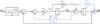 |
Fig. 3 Small signal model for MTD-DCI PLL. |
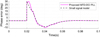 |
Fig. 4 Proposed MTD-DCI PLL, and its small signal model results under a phase jump of 30°. |
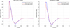 |
Fig. 5 Validate the proposed method with deferent time delay. |
4 Results and discussions
In this part, numerous scenarios are used to evaluate the performance of the proposed single-phase MTD-DCI PLL with the non-adaptive single-phase DSC PLL [12] shown in Figure 6, and single-phase VLTD PLL [9] shown in Figure 7. The non-adaptive single-phase DSC PLL, and the single phase VLTD PLL PI controller gains were designed in accordance with their respective small-signal models. The same (ζ) and  were used as in the proposed PLL to achieve fair comparisons. Based on its small-signal model, the single-phase non-adaptive DSC PLL PI controller gains are computed as follows: kp = 217.193 and ki = 15791.37, whereas the single phase VLTD-PLL gains are computed as kp = 376.98 and ki = 25551.
For the comparisons, the following six cases were considered:
Adding phase jump to the grid voltage.
Changing the grid frequency.
Adding a DC-offset to the input voltage.
Adding a phase jump and a DC-offset at the same time to the grid voltage.
Changing the input voltage amplitude.
Changing the amplitude of the grid voltage and adding a DC-offset at the same time.
MATLAB/Simulink was used to simulate the techniques. The estimated phase error and the estimated frequency for the methods were used in the comparison. The results were presented in Figures 8–19.
A. A phase jump of 30∘ is done at 0.02 s, as indicated in Figure 8.
In this case, the results in Figure 9 show that, the proposed MTD-DCI PLL has the shortest synchronization time where when applying a phase jump of 30° the phase error becomes zero in 48.98 ms while the VLTD PLL was 49.22 ms and the non-adaptive DCS PLL was 52.91 ms. Moreover, the proposed MTD-DCI PLL shows a good estimated frequency where the peak value of the estimated frequency is 54.56 hertz (Hz) while the VLTD PLL was 54.69 Hz and the non-adaptive DSC PLL was 53.54 Hz.
B. jump in the grid frequency is done from 50 to 55 Hz at 0.02 s, as indicated in Figure 10.
In this case, the results indicate that the proposed MTD-DCI PLL outperforms the other methods in terms of synchronization time. When applying a 5 Hz jump in the grid frequency, the proposed MTD-DCI PLL achieves a zero phase error in 39.17 ms, as presented in Figure 11. In comparison, the VLTD PLL requires 41.18 ms, and the non-adaptive DCS PLL requires 58.10 ms to reach the same phase error correction. Additionally, the proposed MTD-DCI PLL demonstrates superior accuracy in estimating the frequency, with the peak value of the estimated grid frequency being 55.09 Hz. On the other hand, the VLTD PLL provides 55.18 Hz, and the DSC PLL provides 55.20 Hz as their respective peak estimated frequencies.
C. A DC-offset is added, at 0.02 s, to the grid voltage with a value of 0.2 pu, (see Fig. 12).
The proposed MTD-DCI PLL rejects the effect of the DC offset in a very short time the results in Figure 13 show that, the phase error becomes zero in 18.85 ms while the VLTD PLL was 18.85 ms and the non-adaptive DCS PLL was 52.80 ms. Moreover, the proposed MTD-DCI PLL shows a very low impact in the estimated frequency where the peak value of the estimated frequency is 50.11 Hz while the VLTD PLL was 50.11 Hz and the DSC PLL was 49.20 Hz.
D. A phase jump of 30∘ and a DC-offset of 0.15 pu are added to the grid voltage at 0.02 s, as indicated in Figure 14.
In this case, the results in Figure 15 show that the proposed MTD-DCI PLL has the shortest synchronization time where when applying a phase jump and a DC-offset to the grid voltage at the same time the phase error becomes zero in 45.49 ms while the VLTD PLL was 47.68 ms and thenon-adaptive DCS PLL was 53.03 ms. Moreover, the proposed MTD-DCI PLL shows a good estimated frequency where the peak value of the estimated frequency is 54.48 Hz while the VLTD PLL was 54.64 Hz and the DSC PLL was 53.53 Hz.
E. A jump in the amplitude of the grid voltage from 1 to 1.1 pu at 0.02 s, as indicated in Figure 16.
In this case, the results in Figure 17 show that the proposed MTD-DCI PLL has the shortest synchronization time where when a jump in the amplitude of the grid voltage was applied at 0.02 s the phase error becomes zero in 48.51 ms while the VLTD PLL was 48.51 ms and the non-adaptive DCS PLL was 56.68 ms.
F. A jump in the amplitude of the grid voltage from 1 to 1.1 pu at 0.02 s with a DC offset of 0.2 Pu added at the same time, as indicated in Figure 18.
In this particular scenario, the outcomes illustrated in Figure 19 show that the proposed MTD-DCI PLL exhibits the fastest synchronization time. When subjected to a sudden increase in grid voltage amplitude with DC-offset at 0.02 s, the phase error reaches zero in 36.62 ms. In comparison, the VLTD PLL and non-adaptive DCS PLL require 36.62 ms and 58.86 ms respectively, to achieve the same phase error correction. Moreover, the proposed MTD-DCI PLL shows the minimum estimated frequency where the peak value of the estimated frequency is 49.73 Hz while the VLTD PLL was 49.71 Hz and the DSC PLL was 49.29 Hz.
Table 1 summarizes the performance comparisons of the proposed MTD-DCI PLL with other PLLs in terms of phase settling time, and the peak of estimated frequency.
The results in Table 1 demonstrate that the proposed PLL exhibits a significantly faster response compared to the other PLLs. Particularly, in case C, when a DC-offset is added to the grid voltage, the proposed PLL quickly rejects the effect of the DC-offset without causing a significant impact on the estimated frequency. Moreover, in cases A, B, and D, the proposed PLL achieve grid voltage lock faster than the VLTD PLL and the non-adaptive DSC PLL.
Considering the comprehensive analysis of results from Figures 8–19 and Table 1, it is apparent that although the proposed MTD-DCI PLL and the VLTD PLL show fairly similar performance, the proposed MTD-DCI PLL outperforms the DSC PLL. It boasts the fastest dynamic response and achieves the shortest synchronization time over all PLLs evaluated. Another significant advantage is that the proposed PLL is not limited to any specific time delay; it effectively rejects the DC-offset at any time delays.
Overall, the study confirms that the proposed MTD-DCI PLL is a highly efficient and adaptable solution, offering quick response and accurate synchronization while different scenarios effectively.
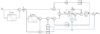 |
Fig. 6 Non-adaptive single-phase DSC PLL. |
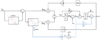 |
Fig. 7 Single phase VLTD PLL. |
 |
Fig. 8 Grid voltage and estimated voltage under case A. |
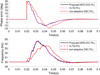 |
Fig. 9 Results under case A. |
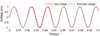 |
Fig. 10 Grid voltage and estimated voltage under case B. |
 |
Fig. 11 Results under case B. |
 |
Fig. 12 Grid voltage and estimated voltage under case C. |
 |
Fig. 13 Results under case C. |
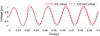 |
Fig. 14 Grid voltage and estimated voltage under case D. |
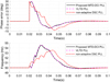 |
Fig. 15 Results under case D. |
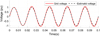 |
Fig. 16 Grid voltage and estimated voltage under case E. |
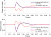 |
Fig. 17 Results under case E. |
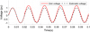 |
Fig. 18 Grid voltage and estimated voltage under case F. |
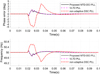 |
Fig. 19 Results under case F. |
Summarizes the cases studied in the comparison.
5 Conclusions
This work suggests a way of removing the impact of the DC-offset in the grid synchronization procedure by proposing a new PLL technique based on TD and DSC operators to generate the orthogonal signal and to reject the DC-offset in the PLLs input. The proposed PLL is not constrained to a particular time delay. The proposed method incorporates a phase error compensator operator aimed at resolving phase shift problem resulting from delayed input signals. The study contains an extensive analysis of the mathematical model, small-signal model, closed-loop stability, and the process of determining the PI controller gains. To validate the small signal model, a comparison with the real-time model was performed. The PI controller gains were calculated by analyzing the real-time and small signal models, then deriving a particular second-order characteristic equation. To evaluate the efficacy of the proposed method, several scenarios were simulated using MATLAB/Simulink. The proposed method was compared with other single-phase PLLs based on performance indicators such as settling time, frequency response, and phase error. The scenarios contained the introduction of various disturbances to the input voltage, including:
Adding Phase Jumps: Sudden shifts in phase to evaluate the PLL's ability.
Introducing DC Offsets: Evaluating how well the PLL handles DC offset in the input voltage.
Changing the Grid Frequency: Assessing the PLL's response to variations in grid frequency, an important factor in grid-connected systems subjected to frequency changes.
Changing the Voltage Amplitude: Studying how the PLL responds to variations in voltage amplitude.
According to the results the proposed PLL has the fastest dynamic response and the shortest synchronization time. Due to its flexibility and benefits over other PLLs the proposed PLL is expected to be very fruitful from industrial point of view. As a direction for future research, the authors propose the development of a novel algorithm aimed at identifying optimal PI controller gains to enhance the system's speed.
Abbreviations
DG: Distributed Generators
RES: Renewable Energy Sources
PLL: Phase Locked Loop
TD: Transfer Delay
DSC: Delay Signal Cancelation
IEA: International Energy Agency
PD: Phase Detector
LF: Loop Filter
VCO: Voltage-Controlled Oscillator
IPA: Inverse Park Approach
SOGI: Second Order Generalized Integrator
KF: Kalman Filter
MAF: Moving Average Filter
A/D: Analog/Digital
SRF: Synchronous Reference Frame
APF: Active Power Filter
TD-OSG: Time Delay-based Orthogonal Signal Generator
RCE: Reference Current Extraction
DCI: DC immune
EPLL: Enhanced PLL
FIR: Finite Impulse Response
VLTD: Variable length TD
CDSC: Cascaded DSC
MTD-DCI PLL: Modified Transfer Delay DC-immune PLL
CE: Characteristic Equation
Nomenclature
υa: Grid voltage
θ: Grid phase
V: Grid amplitude
ωg: Grid frequency
φ: The initial phase angle of grid voltage
 : DC component in the input voltage va
va, vβ: The αβ reference frame voltage components
T: Time period
τ: Delay time
vq: The q reference frame voltage components
^□: Refers to the estimated signals
ωn: Nominal grid frequency
ώn: Natural frequency
ξ: Damping factor
kp, ki: PI controller gains
ms: Milliseconds
Hz: Hertz
pu: Per unit
Implications and influences
The aim of our research is to propose a simple and efficient single-phase phase-locked loop (PLL) method for grid synchronization that can reject DC offset. We provide a small signal model and mathematical representation of our proposed method, which was developed using transfer delay and delay signal cancelation methods with phase error compensators. Our work compares favorably with other PLLs, and we believe that our proposed PLL will have significant industrial benefits due to its flexibility and advantages.
Funding
This research received no external funding.
Conflict of Interest
The authors declare that they have no known competing financial interests or personal relationships that could have appeared to influence the work reported in this paper.
Author Contributions
Conceptualization, M.A.B.I. and P.M.B.B.; methodology, M.A.B.I. and Z.A.A.M.; software, M.A.B.I. and Z.A.A.M.; validation, P.M.B.B. and M.A.B.I.; formal analysis, M.A.B.I.; investigation, M.A.B.I. and P.M.B.B.; resources, M.A.B.I., Z.A.A.M. and P.M.B.B.; data curation, M.A.B.I. and Z.A.A.M.; writing—original draft preparation, M.A.B.I. and Z.A.A.M.; writing—review and editing, M.A.B.I. and P.M.B.B.; visualization, M.A.B.I. and P.M.B.B.; supervision, P.M.B.B.; project administration, P.M.B.B. All authors have read and agreed to the published version of the manuscript.
References
- M.T. Chaichan, M.T. Mahdi, H.A. Kazem, A.H. Al-Waeli, M.A. Fayad, A.A. Al-Amiery, W.N. Isahak, A.A. Kadhum, M.S. Takriff, Modified nano-Fe2O3-paraffin wax for efficient photovoltaic/thermal system in severe weather conditions, Sustainability 14, 12015 (2022) [CrossRef] [Google Scholar]
- A.S. Darwish, Wind energy utilisation for water desalination, street and buildings lighting − a case study for The Emirate of Ajman − UAE, Renewable Energy Environ. Sustain. 6, 10 (2021) [CrossRef] [EDP Sciences] [Google Scholar]
- IEA, Global Energy Review 2020, IEA, Paris. https://www.iea.org/reports/global-energy-review-2020 (2020) [Google Scholar]
- REE, The Spanish Electricity System. Preliminary report 2021 | Red Eléctrica. Available at https://www.ree.es/sites/default/files/publication/2022/04/downloadable/avance_ISE_2021_EN.pdf [Google Scholar]
- G.A. Herrejón-Pintor, E. Melgoza-Vázquez, J. de Chávez, A modified Sogi-PLL with adjustable refiltering for improved stability and reduced response time, Energies 15, 4253 (2022) [CrossRef] [Google Scholar]
- M.A. Bany Issa, Z.A. Al Muala, P.M. Bello Bugallo, Grid-connected renewable energy sources: a new approach for phase-locked loop with DC-offset removal, Sustainability 15, 9550 (2023) [CrossRef] [Google Scholar]
- L. Yang, T. Cao, H. Chen, X. Dong, S. Zhang, Robust control and optimization method for single-phase grid-connected inverters based on all-pass-filter phase-locked loop in weak grid, Energies 15, 7355 (2022) [CrossRef] [Google Scholar]
- I.A. Smadi, H. Altabbal, B.H. Fawaz, A phase-locked loop with inherent DC offset rejection for single-phase applications, IEEE Trans. Ind. Informatics 19, 200 (2023) [CrossRef] [Google Scholar]
- I.A. Smadi, B.H. Bany Fawaz, Phase-locked loop with DC offset removal for single-phase grid-connected converters, Electric Power Syst. Res. 194, 106980 (2021) [CrossRef] [Google Scholar]
- S. Golestan, J.M. Guerrero, A. Vidal, A.G. Yepes, J. Doval-Gandoy, F.D. Freijedo, Small-signal modeling, stability analysis and design optimization of single-phase delay-based PLLs, IEEE Trans. Power Electron. 31, 3517 (2016) [CrossRef] [Google Scholar]
- I.A. Smadi, M.B. Issa, Phase locked loop with DC-offset removal for grid synchronization, IECON 2019-45th Annual Conference of the IEEE Industrial Electronics Society (2019) [Google Scholar]
- S. Golestan, J.M. Guerrero, J.C. Vasquez, A.M. Abusorrah, Y. Al-Turki, Advanced single-phase DSC-based PLLs, IEEE Trans. Power Electron. 34, 3226 (2019) [CrossRef] [Google Scholar]
- B. Aldbaiat, M. Nour, E. Radwan, E. Awada, Grid-connected PV system with reactive power management and an optimized SRF-PLL using genetic algorithm, Energies 15, 2177 (2022) [CrossRef] [Google Scholar]
- H. Ahmed, S. Biricik, M. Benbouzid, Linear Kalman filter-based grid synchronization technique: an alternative implementation, IEEE Trans. Ind. Informatics 17, 3847 (2021) [CrossRef] [Google Scholar]
- A. Sahoo, J. Ravishankar, C. Jones, Phase-locked loop independent second-order generalized integrator for single-phase grid synchronization, IEEE Trans. Instrum. Meas. 70, 1 (2021) [Google Scholar]
- Y. Han, M. Luo, X. Zhao, J.M. Guerrero, L. Xu, Comparative performance evaluation of orthogonal-signal-generators-based single-phase PLL algorithms—a survey, IEEE Trans. Power Electron. 31, 3932 (2016) [CrossRef] [Google Scholar]
- M. Ciobotaru, R. Teodorescu, F. Blaabjerg, A new single-phase PLL structure based on second order generalized integrator, 2006 37th IEEE Power Electronics Specialists Conference, Jeju, Korea (South) (2006) [Google Scholar]
- D. Stojić, N. Georgijević, M. Rivera, S. Milić, Novel orthogonal signal generator for single phase PLL Applications, IET Power Electron. 11, 427 (2018) [CrossRef] [Google Scholar]
- L. Yang, T. Cao, H. Chen, X. Dong, S. Zhang, Robust control and optimization method for single-phase grid-connected inverters based on all-pass-filter phase-locked loop in weak grid, Energies 15, 7355 (2022) [CrossRef] [Google Scholar]
- D. Stojic, T. Tarczewski, L.J. Niewiara, L.M. Grzesiak, Improved fixed-frequency SOGI based single-phase PLL, Energies 15, 7297 (2022) [CrossRef] [Google Scholar]
- S.M. Silva, B.M. Lopes, B.J.C. Filho, R.P. Campana, W.C. Bosventura, Performance evaluation of PLL algorithms for single-phase grid-connected systems, Conference Record of the 2004 IEEE Industry Applications Conference, 2004. 39th IAS Annual Meeting., Seattle, WA, USA. 4, 2259 (2004) [Google Scholar]
- S. Golestan, J.M. Guerrero, J.C. Vasquez, A.M. Abusorrah, Y. Al-Turki, Research on variable-length transfer delay and delayed-signal-cancellation-based PLLs, IEEE Trans. Power Electron. 33, 8388 (2018) [CrossRef] [Google Scholar]
- Z. Dai, Z. Zhang, Y. Yang, F. Blaabjerg, Y. Huangfu, J. Zhang, A fixed-length transfer delay based adaptive frequency-locked loop for single-phase systems, IEEE Trans. Power Electron. 34, 4000 (2019) [CrossRef] [Google Scholar]
- M. Xie, H. Wen, C. Zhu, Y. Yang, DC offset rejection improvement in single-phase SOGI-PLL algorithms: methods review and experimental evaluation, IEEE Access 5, 12810 (2017) [CrossRef] [Google Scholar]
- I.A. Smadi, B.H. Bany Fawaz, DC offset rejection in a frequency-fixed second-order generalized integrator-based phase-locked loop for single-phase grid-connected applications, Protect. Control Modern Power Syst. 7 (2022) [Google Scholar]
- R. Cardoso, R.F. de Camargo, H. Pinheiro, H.A. Gründling, Kalman filter based synchronisation methods, IET Gener. Transmission Distrib. 2, 542 (2008) [CrossRef] [Google Scholar]
- J. Li, Q. Wang, L. Xiao, Y. Hu, Q. Wu, Z. Liu, An αβ-frame moving average filter to improve the dynamic performance of phase-locked loop, IEEE Access 8, 180661 (2020) [CrossRef] [Google Scholar]
- S. Gautam, Y. Lu, S. Taghizadeh, W. Xiao, D.D.-C. Lu, An enhanced time-delay-based reference current identification method for single-phase system, IEEE J. Emerg. Sel. Top. Ind. Electron 3, 683 (2022) [CrossRef] [Google Scholar]
- H. Sepahvand, M. Saniei, S.S. Mortazavi, S. Golestan, Performance improvement of single-phase PLLs under adverse grid conditions: an FIR filtering-based approach, Electric Power Syst. Res. 190, 106829 (2021) [CrossRef] [Google Scholar]
Citation de l’article: Mohammad A. Bany Issa, Zaid A. Al Muala, Pastora M. Bello Bugallo, Simple Solution of DC-Offset Rejection Based Phase-Locked Loop for Single-Phase Grid-Connected Converters, Renew. Energy Environ. Sustain. 9, 4 (2024)
All Tables
All Figures
|
Fig. 1 Single phase SRF-PLL structure. |
| In the text | |
|
Fig. 2 Proposed MTD-DCI PLL. |
| In the text | |
|
Fig. 3 Small signal model for MTD-DCI PLL. |
| In the text | |
|
Fig. 4 Proposed MTD-DCI PLL, and its small signal model results under a phase jump of 30°. |
| In the text | |
|
Fig. 5 Validate the proposed method with deferent time delay. |
| In the text | |
|
Fig. 6 Non-adaptive single-phase DSC PLL. |
| In the text | |
|
Fig. 7 Single phase VLTD PLL. |
| In the text | |
|
Fig. 8 Grid voltage and estimated voltage under case A. |
| In the text | |
|
Fig. 9 Results under case A. |
| In the text | |
|
Fig. 10 Grid voltage and estimated voltage under case B. |
| In the text | |
|
Fig. 11 Results under case B. |
| In the text | |
|
Fig. 12 Grid voltage and estimated voltage under case C. |
| In the text | |
|
Fig. 13 Results under case C. |
| In the text | |
|
Fig. 14 Grid voltage and estimated voltage under case D. |
| In the text | |
|
Fig. 15 Results under case D. |
| In the text | |
|
Fig. 16 Grid voltage and estimated voltage under case E. |
| In the text | |
|
Fig. 17 Results under case E. |
| In the text | |
|
Fig. 18 Grid voltage and estimated voltage under case F. |
| In the text | |
|
Fig. 19 Results under case F. |
| In the text | |
Current usage metrics show cumulative count of Article Views (full-text article views including HTML views, PDF and ePub downloads, according to the available data) and Abstracts Views on Vision4Press platform.
Data correspond to usage on the plateform after 2015. The current usage metrics is available 48-96 hours after online publication and is updated daily on week days.
Initial download of the metrics may take a while.